|
|
Post by Pokahpolice on Apr 5, 2014 22:15:18 GMT -5
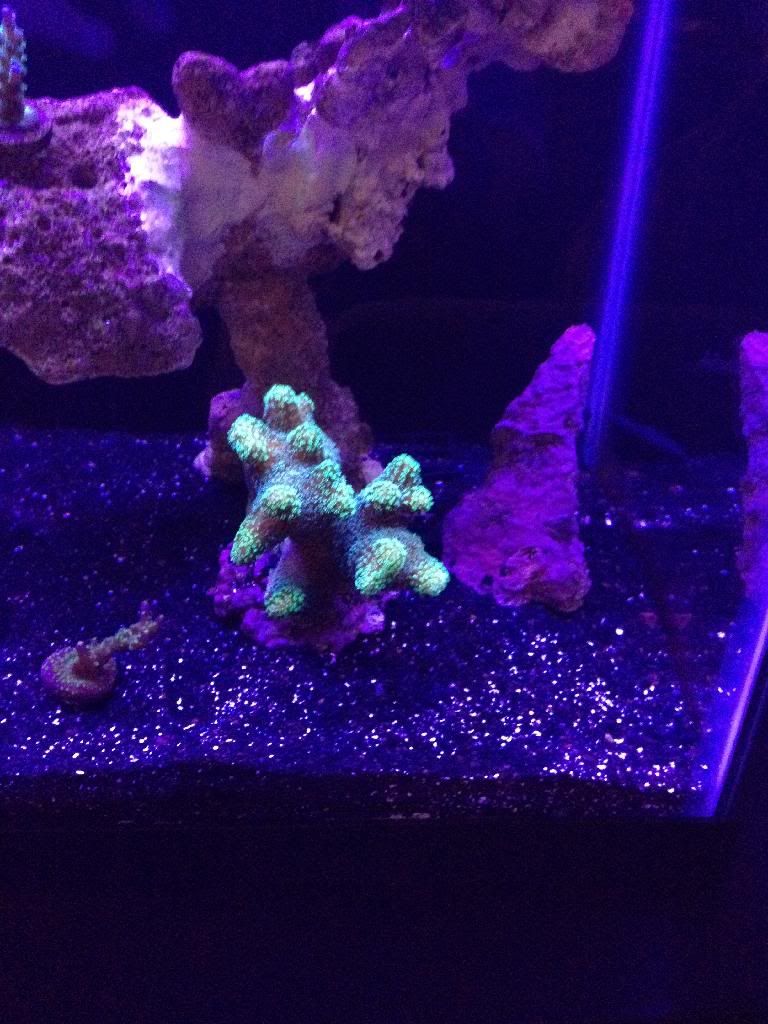
A&M Turquoise Staghorn Acropora from Lance |
|
|
|
Post by Lance on Apr 6, 2014 21:15:14 GMT -5
Glad you like.
|
|
|
|
Post by Pokahpolice on Apr 7, 2014 18:38:24 GMT -5
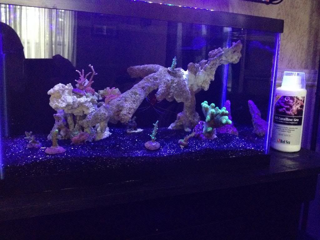
New addition today that I picked up from Easy.   |
|
|
|
Post by Pokahpolice on Apr 10, 2014 13:22:13 GMT -5
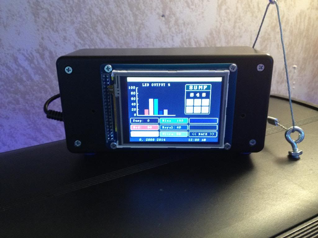
Finally got the touch screen working today. I used the Jarduino v1.1 code and just tweaked it a bit to fit my needs. Now I can control each string with the touch screen, set the dim in and out schedule, the code also has a lunar schedule built in that I haven't played with yet.  |
|
|
|
Post by jasonandsarah on Apr 22, 2014 6:08:14 GMT -5
I totally spaced it until now but..... A couple months ago I was talking to a seller on eBay that was selling a cheap Chinese led (d120) just like mine and many others on here and in the description it said "apex ready", so I messaged him and we talked for a couple days and when I thought of this I didn't know if I could get the info from him if it would be of any help?
I know you had said the only reason you built your leds is because you couldn't figure out how to control the cheaper leds with a controller because, of the drivers?
|
|
|
|
Post by Pokahpolice on Apr 22, 2014 7:10:02 GMT -5
The Apex uses a digital signal to control dimming so it makes sense that it would be compatible. I built an LED fixture for a few reasons but one is because the premade fixtures do not take a PWM signal. This means they are not compatible with the Arduino. I wanted to build a controller so building an LED fixture sort of made sense as well. I actually found a solution yesterday. shop.stevesleds.com/Aquarium-Controller-Interface-Harness-for-Steves-LEDs-Drivers-harness.htm This will convert an Analog signal to PWM for four channels. Only problem is that it costs $45 for four channels which completely kills the budget. Might as well buy an Apex. |
|
|
|
Post by jasonandsarah on Apr 22, 2014 8:29:35 GMT -5
The Apex uses a digital signal to control dimming so it makes sense that it would be compatible. I built an LED fixture for a few reasons but one is because the premade fixtures do not take a PWM signal. This means they are not compatible with the Arduino. I wanted to build a controller so building an LED fixture sort of made sense as well. I actually found a solution yesterday. shop.stevesleds.com/Aquarium-Controller-Interface-Harness-for-Steves-LEDs-Drivers-harness.htm This will convert an Analog signal to PWM for four channels. Only problem is that it costs $45 for four channels which completely kills the budget. Might as well buy an Apex. So an apex by out self can control the leds I have? Could you explain please? Do you know how it works on the apex? |
|
|
|
Post by Pokahpolice on Apr 22, 2014 9:18:52 GMT -5
Compatible is a relative term. Yes, your fixture uses an analog signal to dim the LEDs. The Apex also uses an analog signal which means in theory they should be compatible. The question then becomes does your fixture have the inlet (plug) to hook up the Apex. I doubt it does. So now you need to take the fixture apart and add the necessary connection. So your fixture is not Apex 'ready' but MAY be compatible.
I haven't done much research on the Apex so I don't know what's required. Does the Apex have a library of compatible fixtures? Are separate drivers necessary? Is it simply a connection issue or is there a serial interface that is required?...All things that need to be researched and understood.
|
|
|
|
Post by jasonandsarah on Apr 22, 2014 9:48:51 GMT -5
They have a Neptune apex forum and there's a section on diy I believe? That'll probably be my best bet
|
|
|
|
Post by foggman on Apr 22, 2014 13:08:48 GMT -5
The LEDs you have use a analog 0-10v for dimming, if the apex can send out 0-10v analog signal that you would need to remove the wire connector from the control knob in the LED and make a connector to connect it to the apex, on mine there is 3 wires, + - and on. You would also need to find a way to send power to the on terminal. I am about 90% of the way to making the arduino talk to it, I know how to do it just trying to find what combo of components to use to make it work right
|
|
|
|
Post by jasonandsarah on Apr 22, 2014 13:26:54 GMT -5
HOW to set up the Apex to dim my DIY LEDs below 10% to simulate moonlights? forum.neptunesystems.com/showthread.php?t=1979HOW to set up the Apex to dim my DIY LEDs below 10% to simulate moonlights? I know this thread is different then what everyone is trying to do but isn't it kinda the same concept? |
|
|
|
Post by Pokahpolice on Apr 22, 2014 13:45:38 GMT -5
HOW to set up the Apex to dim my DIY LEDs below 10% to simulate moonlights? forum.neptunesystems.com/showthread.php?t=1979HOW to set up the Apex to dim my DIY LEDs below 10% to simulate moonlights? I know this thread is different then what everyone is trying to do but isn't it kinda the same concept? This isn't a solution. In this thread he is replacing the drivers to LDDs which are the same drivers I used in my light. They are PWM compatible. They cost about $8-$10 each and you need one for each string you want to control. You also need the converter that I posted earlier. The converter is $45.00 for four channels plus $40 for the drivers and we're up to $85...ohh and the driver board he posted, another $18. Next, you just replaced your drivers with ones that do not have a power supply (PSU). You need to find a PSU that will put out enough juice but still fit in the fixture. Another $30-$40. Basically you would need to completely rebuild your fixture and spend about $150 to go this route. |
|
|
|
Post by jasonandsarah on Apr 22, 2014 16:55:52 GMT -5
|
|
|
|
Post by Pokahpolice on Apr 22, 2014 18:11:10 GMT -5
Did your Apex come with the VDM module? I didn't read the entire thread but in the video he hooked it directly to the module. Without doing some research I don;t clearly understand the wiring but this is what he describes..
"So it seems all you need to do to control it is to get a little 4 pin header, unplug the pot board, short out pins 1-2 to power it on, then hook up pins 3 and 4 to the + and - wires coming out of the Apex VarSpd port. Or just snip off the connector and solder the wires together. Ooh, or cut a little square in the metal panel on the top and put a keystone RJ45 jack, then you could just use a Cat5 patch cable to go between the Apex and the d120."
Seems to work...
|
|
|
|
Post by jasonandsarah on Apr 22, 2014 19:21:54 GMT -5
Would you recommended? I have small children so I'm not taking any chances on faulty wiring again.
I'll leave you alone after this.....Maybe lol
|
|